
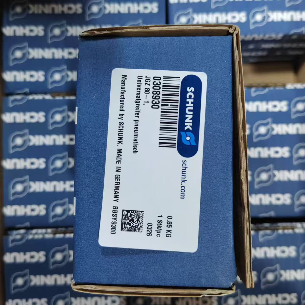
At a Glance. Almost every SCHUNK gripper can be fitted with position sensing, and the catalogue offers two different principles for the job: magnetic switches in the MMS family, and inductive proximity switches in the IN family. They are not interchangeable, and the choice is settled by the jaw design rather than by preference. The magnetic MMS 22-S-M8-PNP is the standard answer for a T-slot machined into the gripper body; the inductive IN 5-S-M8 is used where a magnet cannot be fitted to the moving part. Both principles are held in the SCHUNK range, alongside the gripping systems they monitor.
1. What a gripper sensor actually has to prove
A gripper sensor answers one question for the controller: is the jaw where it should be? That sounds trivial until the consequences are traced. A machine tending cell that starts a transfer while the gripper is only part-closed damages the part, the gripper or both. A press that closes on an unconfirmed clamp produces scrap. The sensor is therefore a safety and sequencing input, not a convenience.
Two mechanical facts follow from that:
- The sensor must detect the end position of the movement, not an intermediate one, because only the end position is repeatable.
- The sensor must do so without contact and without wear, because a gripper may cycle several million times over its life.
Contactless sensing is why the choice narrows to two principles rather than one: measure the magnetic field of a magnet attached to the moving part, or measure the metal of the moving part directly.
2. Magnetic switches: the MMS family
The MMS family works by sensing a permanent magnet that moves with the piston or jaw. The switch sits in a profile slot in the gripper body, or is clamped in the slot and adjusted along it, so the switching point can be positioned exactly at the end of travel. Nothing touches the moving part, and no target needs to be machined into it — the magnet is part of the gripper mechanism.
That is why MMS switches are the default on a SCHUNK gripper: the slot and the magnet already exist by design, so sensing is a matter of selecting the right switch and sliding it to the correct position.
Variants you will meet
- MMS 22 — the standard body size for the common gripper range, in PNP or NPN output and with an M8 or M12 connector, for example the MMS 22-S-M8-PNP in stock.
- MMSK 22 — the shorter body, used where the slot is too short for a standard switch, such as the MMSK 22-S-PNP held in stock.
- MMS-P 22 — a variant body referenced in the same family, available as the MMS-P 22-S-M8-PNP.
- MMS 30 — the larger size for bigger grippers, for example the MMS 30-S-M8-PNP.
- -SA suffix — a different cable or connection arrangement on the same sensing body, such as the MMS 22-S-M8-PNP-SA.
- IOL — the IO-Link variant, which reports switching state and diagnostics as data instead of as a single digital signal: MMS 22-IOL-M08 and its M12 equivalent, MMS 22-IOL-M12.
The IO-Link version is worth the extra thought on a cell that is already networked. Instead of one wire per switch back to the cabinet, the switch becomes a device on the segment, and a failing sensor can be identified by port rather than by elimination.
3. Inductive switches: the IN family
An inductive switch detects metal directly, using the same eddy-current principle as an inductive proximity sensor anywhere else in the plant. There is no magnet to sense, so the switch responds to the moving component itself or to a target feature on it.
Use the IN family when the magnet route is not available. Typical reasons: the moving part is non-magnetic or cannot be modified; a magnet adjacent to the working area is unacceptable because it would collect swarf or disturb a nearby sensor; or the sensing position must be outside the gripper body rather than inside a profile slot.
Typical examples in the range are the IN 40-S-M8 and the longer-range IN 80-S-M8, with the M12 connector version of the smaller body available as the IN 40-S-M12-SA. As with the magnetic family, the body sizes and connector options exist to suit the mounting space rather than to change the sensing principle.
4. MMS against IN: the decision table
| Question | MMS magnetic | IN inductive |
|---|---|---|
| Does the gripper have a profile slot and a built-in magnet? | Yes — use MMS | Not applicable |
| Can a magnet be fitted to the moving part? | Yes — use MMS | Not required |
| Is swarf or ferrous dust present near the jaws? | Magnet will attract it | Preferred |
| Must sensing avoid a magnetic field, e.g. near welding or magnetic clamping? | Not suitable | Preferred |
| Is the switching point finely adjustable along a slot? | Sliding adjustment | Set by target position and gap |
| Is IO-Link diagnostics required? | Available via the IOL variants | Depends on the model |
The table resolves most enquiries in one line. If the gripper is a standard SCHUNK unit with a T-slot, the answer is an MMS switch and the only open questions are body size and output type. The IN family is the exception path, chosen because of the environment or because the moving part cannot carry a magnet.
5. Output, connector and supply — the details that stop a project
Sensing principle is the visible decision; the electrical details are the ones that cause a return.
- PNP or NPN. This must match the input card on the controller. A PNP sensor into an NPN input is a silent failure and appears as a gripper that never confirms. Both variants exist across the range, for example the MMS 22-S-M8-NPN-SA alongside the PNP bodies.
- Connector size. M8 and M12 bodies are different articles, not adapters, as the pairing of IN 5-S-M8 with the M12 versions shows.
- Body length. The standard and short bodies are distinct part numbers. Specifying a standard body into a short slot means the switch cannot be positioned at the end of travel, which defeats the purpose.
- Two switching points. Some applications need both open and closed confirmed from one body; the PI1 and PI2 versions, such as the MMSK 22-PI1-S-PNP, provide the additional switching output rather than requiring a second switch.
- Supply and temperature. Confirm the switching voltage and the ambient rating at the mounting position before ordering.
6. What is held in stock
There is no need to wait on a lead time for the common combinations. The following are on our shelf as this is written:
| Part | Principle | Stock reference |
|---|---|---|
| MMS 22-S-M8-PNP | Magnetic, PNP | view stock |
| MMSK 22-S-PNP | Magnetic, short body | view stock |
| MMS-P 22-S-M8-PNP | Magnetic, P variant | view stock |
| MMS 22-S-M8-PNP-SA | Magnetic, SA variant | view stock |
| MMS 30-S-M8-PNP | Magnetic, MMS 30 body | view stock |
| IN 40-S-M8 | Inductive | view stock |
| IN 80-S-M8 | Inductive, longer range | view stock |
| IN 40-S-M12-SA | Inductive, M12 | view stock |
7. Choosing, in order
- Identify the gripper. Take the model and the jaw configuration, because that determines whether a magnet is already present and where it is.
- Decide the principle. MMS where a magnet and a slot exist; IN where the environment or the moving part rules a magnet out.
- Fix the body size and length. Standard or short, MMS 22 or MMS 30 — driven by the slot, not by the sensing distance alone.
- Match the output. PNP or NPN against the controller input card, plus normally-open or normally-closed behaviour.
- Choose the connector. M8 or M12, in line with the cables already used on the cell.
- Consider IO-Link if the cell is networked and sensor-level diagnostics have real value in maintenance.
Send us the gripper model, the controller input type and the connector already in use, and we will propose the matching sensor and quantity from the SCHUNK range as one quotation. For the shaft vibration measurement that underpins the machines these grippers serve, our guide to Bently Nevada 3300 XL proximity probe chains covers the equivalent selection logic on the condition-monitoring side.