
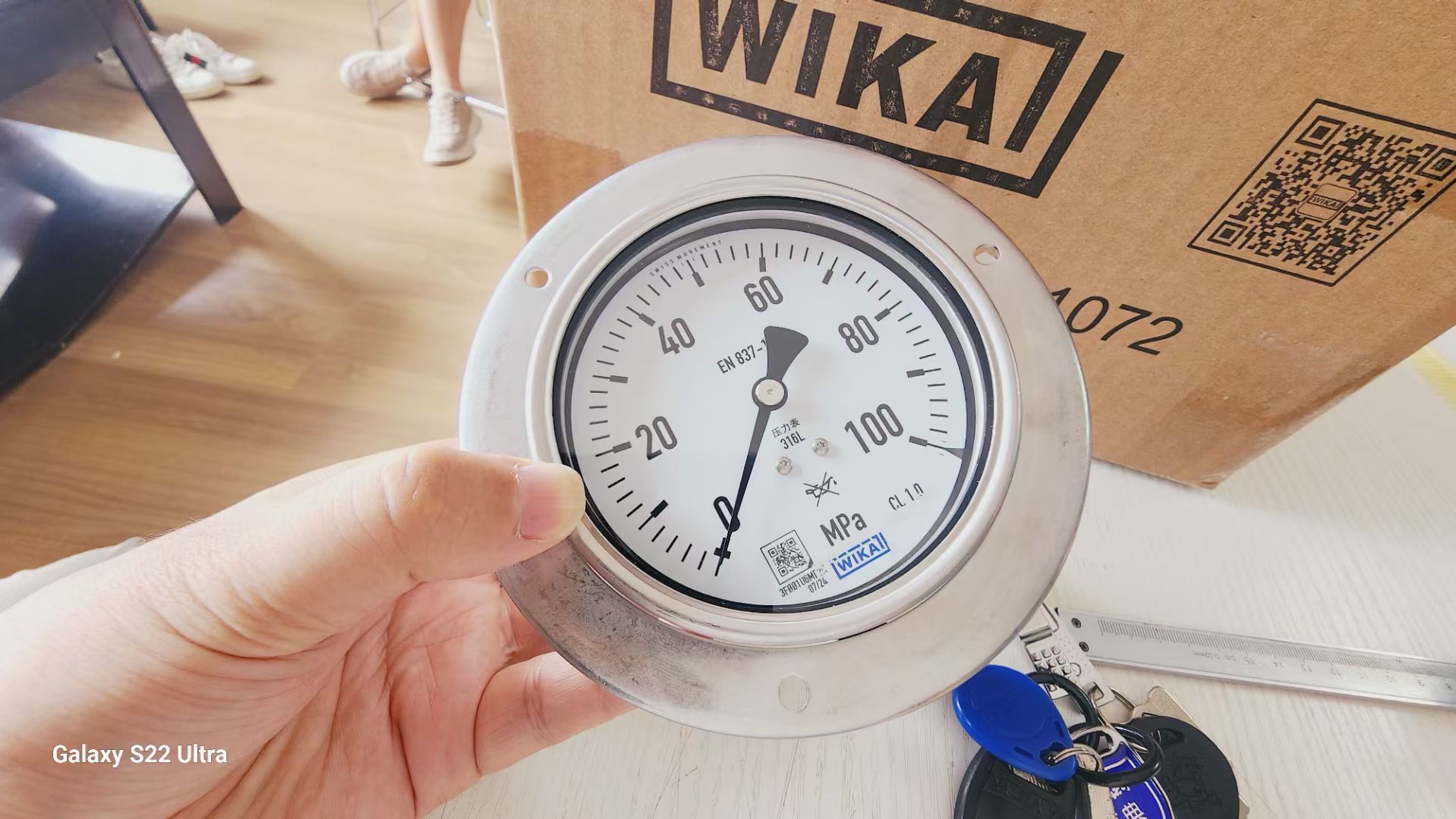
At a Glance. A force transducer and a load cell both produce a millivolt-per-volt signal, both mount with a few screws, and both end up connected to the same kind of amplifier. That is where the similarity stops. This guide covers the 96 WIKA items under force measurement: miniature compression transducers from 0…10 N, high-accuracy units to 0…300 kN, hydraulic transducers that are read from a pressure gauge, single point load cells up to 300 kg, and the mounting parts and junction boxes that make the chain work.
1. Force Transducer or Load Cell: The Core Difference
The confusion is understandable, because the two devices share a sensing principle. Both use a strain gauge bridge bonded to a metal body; both are excited with a few volts and both return a signal of roughly 2 mV/V at full scale. The difference is what the body is designed to tolerate.
A force transducer is built to measure a force along one defined axis, applied by a fixture that the designer controls. A load cell is built to measure weight through a structure — a platform, a hopper, a silo — which means it has to tolerate side loads, off-centre loading, lift-off, and the thermal movement of a large steel vessel. It also has to do it to a legal-for-trade accuracy, which is why load cells are the parts that carry OIML R60 classifications.
| Property | Force transducer | Load cell |
|---|---|---|
| Typical mounting | Fixed fixture, single-axis input | Platform or vessel, allowance for movement |
| Side load tolerance | Low — must be guided mechanically | High — part of the design requirement |
| Accuracy classes | Linearity stated as % of full scale | OIML R60 class and interval count |
| Accessories needed | Cable, sometimes a charge amplifier | Mounting parts, junction box, summing electronics |
| Typical use | Press force, clamping force, test benches | Scales, hoppers, silos, checkweighers |
Where the decision is actually made
The choice is not made by the measuring range. A 0…5 kN force transducer and a 0…5 kN load cell can both exist and both be correct. The decision is made by the structure the device has to survive. If the device is bolted into a press frame that constrains the axis of loading, a force transducer is the right answer and will be more accurate and cheaper. If it is holding up one corner of a vessel that expands by several millimetres when it is filled with hot product, a load cell is the only answer, because a transducer would be destroyed by the first thermal cycle.
2. Miniature Compression Force Transducers: The F11xx Range
The F11xx family covers the small end. These are compact bodies intended for presses, test benches and joining operations, where the force has to be measured in a space that is measured in millimetres.
| Reference | Measuring range | Linearity | Protection |
|---|---|---|---|
| F1101 | 0…10 N to 0…5,000 N | 1 % Fnom | IP65 |
| F1115 | 0…10 N to 0…5,000 N | 1 % Fnom | IP65 |
| F1222 | 0…10 N to 0…5,000 N | 1 % Fnom | IP65 |
| F1103 (hydraulic) | 0…1.1 kN to 0…180 kN | ±1.0…1.6 % Fnom | See section 4 |
Why the range starts at 10 N
A lower bound of 0…10 N is unusual in industrial measurement and it is worth understanding. At that range the transducer is measuring the force of a small spring, a seal, or the drag of a single component — work that is normally done with a laboratory balance. The F11xx parts are designed for that duty in a production environment rather than on a bench, which is why they are sealed to IP65 and built with a low installation height. The same body is then used across two and a half decades of range, up to 5,000 N, so a machine that uses three different sizes of the same transducer only needs one fixture design.
The 1 % linearity figure is the number that decides whether this family is suitable. For press-force monitoring, joining-force verification and control-system feedback, 1 % of full scale is normally sufficient and the low profile is worth more than the accuracy. For anything that has to be traceable to a reference, the figure is not sufficient and the F18xx family in the next section is the starting point.
3. Heavy-Duty and High-Accuracy: F1811 and F1201
Two parts carry most of the load in this range, and they solve two different problems.
| Reference | Measuring range | Linearity | Construction | Protection |
|---|---|---|---|---|
| F1811 | 0…2.5 kN to 0…300 kN | 0.1 % Fnom | Stainless steel, fully welded | IP67 |
| F1201 | 0…5 t to 0…30 t | 1000 intervals, OIML R60 Class C | Stainless steel, hermetically sealed, welded | IP68 |
F1811: ten times the linearity of a standard transducer
At 0.1 % of full scale the F1811 is an order of magnitude more linear than the F11xx parts. It is also fully welded in stainless steel, which matters more than the IP number: a welded body has no gasket to age, no cavity to fill with condensate and no elastomer seal to degrade in a washdown or an outdoor installation. The typical applications follow directly — measuring and control systems, production lines, presses and platform scales for trucks. In each of these the transducer is the reference in a chain that has to be trusted for years, and the welded body is what buys that trust.
F1201: designed for a vessel, not a fixture
The F1201 is a different animal. Its measuring ranges are given in tonnes rather than kilonewtons, its accuracy is expressed as 1,000 intervals to OIML R60 Class C, and its listed applications are vessels with low installation height, silo scales, lifting platforms and stage construction. Those are all cases where the transducer is part of a structure that moves.
The 30 t version at IP68 is hermetically sealed and welded precisely because silo and outdoor weighing applications see rain, washdown and condensation on a daily basis. A gasketed enclosure with an IP67 rating will pass a laboratory test and fail in the second winter. When the load cell is the only thing holding a vessel up, the sealing method is a structural specification, not a cosmetic one.
Reading an OIML R60 class
The interval count is the part of the classification that people skip. Class C with 1,000 intervals means the cell can be used in a weighing instrument with 1,000 divisions — a scale that resolves 1 part in 1,000 of its range. A larger interval count means the same physical cell could be used in a more finely divided instrument, but only if the whole system — mechanics, electronics and installation — supports it. Buying a higher class than the structure can deliver is a common and expensive mistake.
4. Hydraulic Force Transducers with Pressure Gauge Readout
The F11xx series also contains a group of hydraulic transducers that behave quite differently from the strain-gauge units. Instead of a bridge output they contain a hydraulic chamber, and the applied force is read as pressure on a gauge or a pressure sensor.
| Reference | Measuring range | Typical application | Readout accuracy |
|---|---|---|---|
| F1103 | 0…1.1 kN to 0…180 kN | Clamping force in three-jaw chucks | ±1.0…1.6 % analogue, ±0.5 % digital |
| F1119 | 0…320 N to 0…120 kN | Vices and clamping systems, flattened case | ±1.0…1.6 % analogue, ±0.5 % digital |
| F1125 | 0…4 kN to 0…400 kN | Geotechnology and special civil engineering | ±1.0…1.6 % analogue, ±0.5 % digital |
| F1145 | 0…6 kN to 0…850 kN | Equipment manufacturing, jigs and fixtures | ±1.0…1.6 % analogue, ±0.5 % digital |
The accuracy depends on what you read it with
Every part in this group carries two accuracy figures. With an analogue pressure gauge the relative linearity error is ±1.0 to 1.6 % of full scale; with a digital pressure gauge or a pressure sensor it improves to ±0.5 %. Nothing about the transducer changes. The instrument reading the hydraulic pressure is the limiting element, and that gives the user a genuinely useful upgrade path: the same measuring cell in the same fixture becomes twice as accurate simply by replacing the gauge.
850 kN with no supply voltage
The F1145 reaches 0…850 kN and operates without any supply voltage. A piston stroke of no more than 0.5 mm produces the pressure that is displayed. This matters in three situations: where a cable run to the measuring point is impractical, where the machine is moved between sites, and where the environment is electrically noisy enough that a millivolt signal would need heavy filtering. A hydraulic cell does not care about electromagnetic interference, and it cannot be damaged by a wiring error.
Clamping force measurement on a three-jaw chuck is the classic example. The transducer is loaded in a lathe chuck that rotates, the cable routing is awkward and the coolant is everywhere. A hydraulic cell with a gauge on the headstock answers the question the operator actually has — is the workpiece gripped firmly enough — without any electronics at the point of measurement.
5. Single Point Load Cells: F4801 and F4883
Single point load cells are the workhorses of platform weighing. The name describes the mounting: the cell is fixed at one end and the load is applied at the other, and the construction allows the platform to sit anywhere over the cell without introducing a significant error.
| Reference | Measuring range | Material | Notable property |
|---|---|---|---|
| F4801 | 0…3 kg to 0…250 kg | Aluminium alloy | High side load tolerance, simple structure |
| F4883 | 0…8 kg to 0…300 kg | Aluminium | Fast response, low settling time |
F4801: the general-purpose platform cell
The F4801 is aimed at electronic precision scales and industrial weighing systems, with ranges from 3 kg to 250 kg in an aluminium alloy body. The two properties worth noting are high side load tolerance and a simple structure. Both are installation properties rather than measurement properties: they describe how forgiving the cell is when the platform is loaded off-centre, when the frame is not perfectly level, and when the installer has limited time. For a bench scale or a small platform that is assembled on site, that forgiveness is worth more than a better linearity figure that the mechanics cannot deliver.
F4883: built for speed
The F4883 covers 8 kg to 300 kg and its distinguishing property is response speed — a low settling time after a load change. That is a specification written for checkweighers, belt weighers, filling machines and dosing systems, where the cell has to settle before the product has moved on. In a checkweigher running several items per second, a cell that takes 200 ms longer to settle directly becomes throughput lost, and no amount of filtering in the electronics recovers it.
For both parts, the aluminium body is a deliberate choice. Aluminium is cheaper and lighter than stainless steel and perfectly adequate for a dry, indoor bench or platform scale. It is the wrong material for a washdown area, which is where the stainless steel F12xx and F18xx bodies come back in.
6. Load Cell Accessories: Mounting Parts and Junction Boxes
A load cell on its own is not a weighing system. It needs to be held in a way that lets the structure move while keeping the load on the correct axis, and its signal usually has to be combined with that of two or three other cells before it reaches the electronics.
| Reference | Function | Key data |
|---|---|---|
| AZK03 | Load cell mounting parts | 5…500 kg, stainless steel, lift-off protection, horizontal installation |
| AZK02 | Load cell mounting parts | Companion size in the same family |
| B6578 | Junction box | 4-channel, stainless steel, IP67, passive mV/V inputs |
| B6494 | Junction box | Companion size in the same family |
Mounting parts are specified, not improvised
The AZK series parts exist because the mechanical interface of a load cell is a specification. A cell rated for 5…500 kg with lift-off protection and horizontal installation is designed to be held by a specific bracket that allows the vessel to move vertically while preventing it from being lifted off the cell. A welded bracket of the same dimensions will hold the cell and will also destroy the measurement, because it constrains the movement the cell is designed to measure.
Note that the mounting parts are supplied without the load cell. This is deliberate: it lets the same bracket be used with different cell capacities as a vessel is resized, and it means the spare parts stock is smaller. When ordering a complete weighing installation, both lines have to be on the order.
The junction box is where mV/V signals meet
The B6578 is a four-channel stainless steel junction box rated IP67 that connects up to four force transducers or load cells in parallel. It accepts passive millivolt-per-volt inputs and services the parallel connection used in industrial weighing technology. It is a passive summing box, not an amplifier — the summing electronics or the weighing terminal sits downstream.
The reason this matters is cable length. Each load cell has its own cable running to a convenient point, and the junction box is where those four cables are trimmed and combined. Putting the box in the field rather than in the cabinet keeps the individual cable runs short, which keeps the excitation drop and the noise pickup low. An IP67 stainless steel enclosure lets the box be mounted on the vessel leg where the cables are shortest, which is exactly where it should be.
7. High-Capacity Systems and Certified Safety Applications
Two parts in this range sit above the general-purpose cells, and they exist because their applications are regulated rather than merely demanding.
| Reference | Function | Capacity | Certification |
|---|---|---|---|
| WSGC-02 | Load cell | Up to 3,000 kg | Stainless or alloy steel housing |
| ELMS1 | Force measurement system for cranes | Application-specific | DIN EN ISO 13849-1, PLe |
WSGC-02: three tonnes, two housing options
The WSGC-02 reaches 3,000 kg and is offered with either a stainless steel or an alloy steel housing. The applications listed are industrial weighing, level measurement of liquefied gas in gas cabinets and gas distribution systems, and level measurement in chemical delivery systems. All three share a feature: the measurement is used for inventory or for process control on a vessel that cannot be opened. The choice between stainless and alloy steel is then a corrosion decision driven by the product being weighed and the environment around the vessel, not a load decision.
Why a crane force system carries a safety certificate
The ELMS1 is listed for harbour cranes — RTG, STS and RMG — ship and offshore cranes, overhead travelling and bridge cranes, gantry cranes and hoists, conveyor systems and general plant construction. It is a certified system solution, certified according to DIN EN ISO 13849-1 at performance level PLe, combining certified safety electronics with the force measurement itself.
The certification is the point. On a crane, an overload reading is not process information, it is a protective function. When the measurement is what prevents a lift from exceeding the safe working load, the measuring chain has to be part of the validated safety function, with the diagnostics, the fault detection and the documentation that PLe requires. A general-purpose load cell with the right capacity cannot simply be substituted, even if the numbers match, because the safety case depends on the certificate.
8. Accuracy, Linearity and Temperature Effects
Force measurement datasheets use several accuracy terms that are not interchangeable, and mixing them up leads to a system that is two or three times worse than the specification suggested.
- Relative linearity error, expressed as % Fnom — the deviation from the ideal straight line over the range, as a percentage of the nominal full-scale force. The F11xx parts sit at 1 %, the F1811 at 0.1 %.
- OIML R60 class and interval count — a legal-for-trade classification that covers the cell's behaviour over temperature, not just its linearity at a reference temperature.
- Temperature effect on zero and on span — normally quoted per 10 K. This is the term that decides whether a cell outdoors in a European winter will hold its class.
- Side load and eccentricity tolerance — not an accuracy figure but the property that decides whether the structural accuracy you designed for survives contact with a real platform.
The reason a hydraulic cell can hold ±0.5 % with a digital gauge and a strain-gauge cell has to be read from a graph of linearity is simply that the two error mechanisms are different. A hydraulic cell's accuracy is dominated by the gauge that reads it; a strain-gauge cell's is dominated by the bridge and the body. Neither is better in the abstract. What matters is which error term is the limiting one in your installation.
Temperature is the term most often ignored. A transducer selected at 0.1 % linearity and installed on a press whose frame grows by 0.5 mm between a cold morning and a warm afternoon will not deliver 0.1 % of anything, because the fixture is loading the cell in a direction it was not designed for. Correct mechanical design and correct temperature compensation on the cell are both required.
9. Ordering Checklist
Before ordering a force measurement chain, confirm each of the following:
- Structure type — a constrained fixture points to a force transducer, a moving vessel points to a load cell
- Measuring range — chosen with headroom above the working force, and reading the lower bound as carefully as the upper one
- Accuracy term — linearity in % Fnom for control applications, an OIML R60 class for anything that is weighed for trade
- Environment — aluminium for a dry bench, welded stainless steel with IP67 or IP68 for washdown, outdoor or silo duty
- Readout — a millivolt bridge output signalling to an amplifier, or a hydraulic cell read from a gauge where no supply can be routed
- Mechanical interface — the correct mounting parts, ordered separately, allowing the movement the cell is designed to measure
- Signal summing — the right junction box, mounted in the field near the cells rather than in the cabinet
- Safety case — where the measurement is a protective function, a certified system such as the PLe-rated crane solution rather than a standard cell
Send us the force to be measured, the structure it acts on, the accuracy the process needs and the environment the device will live in, and we will confirm the exact WIKA order numbers within 24 hours. Start from the quotation form, or browse the full WIKA range, the wider pressure measurement group, and the companion guide to WIKA pressure gauges versus diaphragm seals if the same project also covers pressure. If your panel work includes the electrical distribution side, the new guide to Socomec distribution accessories covers busbars, cage terminals and fuse bases.
Force measurement rewards a five-minute decision made properly. The transducer is usually a small part of the machine's cost and a large part of whether the machine can be commissioned on time — and unlike almost everything else in the cabinet, it cannot be adjusted after the fact.